RSU
ROTATION SENSOR UNIT
Product description
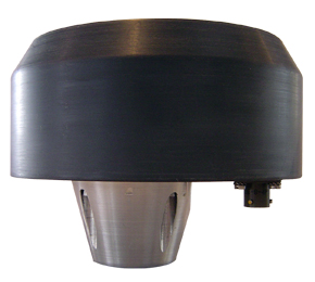
The RSU Rotation Sensor Unit is designed in order to measure the relative or absolute rotation angle of a rotating turret on a mobile machine , such as excavators , cranes or access platforms . Where the rotation is not mechanical limited The particularity of this sensor is that the measured angle is not related to a mechanical displacement between the turret and the chassis of the machine , but with respect an absolute direction angle . In order to obtain such a feature , a multi-axis magnetometer device is used . The operating principle is then based upon the detection of the earth magnetic field variation according to the orientation of the device in the horizontal plane. In order to compensate the magnetic offsets caused by the huge magnetic masses of such kind of machines , a calibration procedure , executed by means of a microcontroller located on a main board , is able to calculate the offsets of the magnetic field caused by the iron mass and then store the resultant values on the magnetometer handling processor memory .
Data sheet
INTERFACES CONFIGURATION
Output
CAN BUS 2.0B; CAN OPEN protocol supported
Connections 4 Poles connector
A = + V, B = Gnd, C = CANL , D = CANH
Programmability
Baud Rate (50, 100, 125, 250, 500, 1000 Kbit/sec.)
Identifier Range
Freely programmable 11-29 bit
Transmission Rate
Freely programmable in 20 ms steps
Output data
0 3600 (0.1 degrees resolution)
Measuring Range
0 360° Continuous
Zero Angle Reference
Freely programmable
Accuracy and Linearity
2 full range without magnetic interferences
ELECTRICAL CHARACTERISTICS
Operating Power Supply Voltage
9-30V DC
Logic current consumption
50-70mA
The Can Bus Interface
By means of the CAN BUS interface the sensor is sending the information about the rotation angle , rotational speed as well as alarm messages.
The CAN BUS version is the 2.0B , supporting standard and extended identifiers.
The available protocol could be proprietary or CAN OPEN.
Identifiers, baud rate damping and transmission rate are fully programmable. Refer to the User Manual for details.
The CAN interface is also used to calibrate the sensor. This procedure is necessary because of the distortion caused by huge magnetic iron masses crated by the booms , engines , counterweights , hoods . After the sensor is fitted on the machine , it is necessary to start first with the magnetic compensation ( activated by a CAN BUS message ) , consisting into a complete CW or CCW rotation . After this procedure , whose accuracy is monitorized by CAN message , a second calibration is necessary , in order to achieve the final accuracy .
This "on fly" calibration is using the integrated gyroscope , and could be used also during normal operation in order to compensate "occasional" magnetic disturbances i.e. a big truck
Installation precautions
Keep the sensor at least 70 cm above from fixing surface ( typical is the rear hood of an excavator turret ) by means of an appropriate aluminium or non magnetic mast .
In case excessive vibrations , insert a shock absorber part between the mast and the fixing surface.
The horizontal distance between the sensor and other obstacles ( cabin , booms , trucks ), should at least 3mt.
MECHANICAL CARACHTERISTIC AND RATINGS
Operating Temperature Range
- 20 C to + 70 C
Storage Temperature Range
- 35 C to + 85 C
Device Vibration
5g from 10 to 500 Hz, 7,5mm over 20 hours for each axis; shock: 25g, 6ns pulse
Enclosure and Connector Protection
IP67